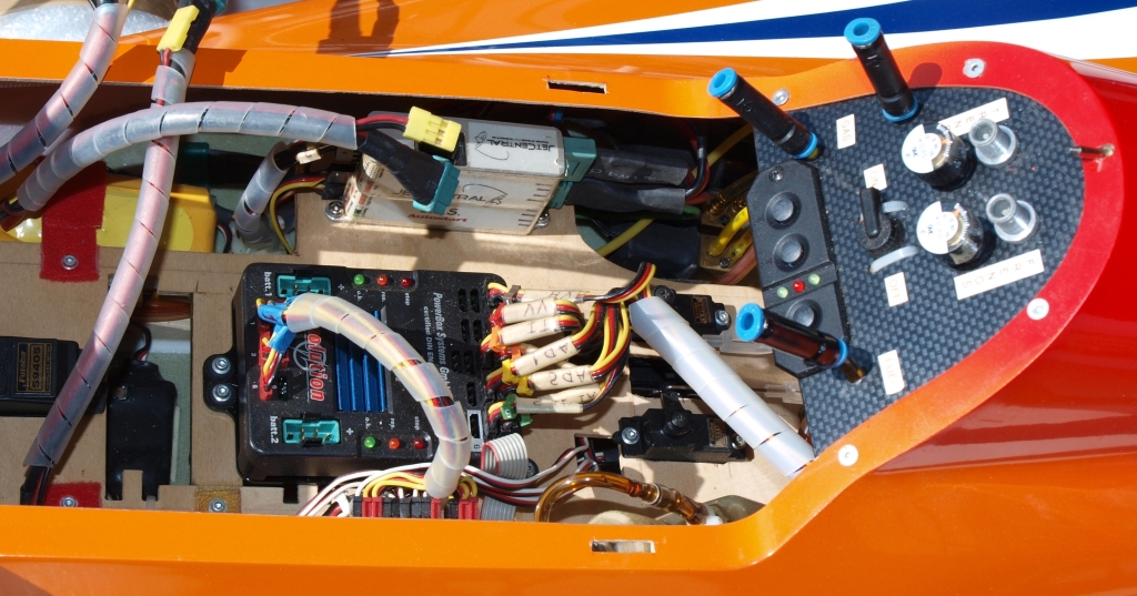
The PowerBox Evolution is always the first choice when a small, robust battery backer system is required: the typical range of applications extends from warbirds to 3D aerobatic models and even to jets
Features
- 6 channels
- Signal amplification and interference suppression for all 16 outputs
- double-regulated output voltages for receivers and servos
- regulated voltage with selection facility, 5.9V or 7.4V
- Separate voltage display for each battery
- Minimum value memory alerts the user to voltage collapses
- Large-area heat-sinks for high regulator performance
- Regulator monitoring, regulator error indicator
- Support for three battery types: LiPo, NiMH / NiCd, LiFePo
- Suppression of any servo feedback currents which may occur
|
|
Technical Data
| Operating voltage
|
4.0V - 9.0V
|
| Power supply
|
2S LiPo, 2S LiIon, 2S LiFePo, 5S NiCd/NiMH
|
| Current drain Power-on state
|
80mA
|
| Current drain Standby
|
4µA
|
| Maximum load current
|
Peak 2x20A
|
| Drop-out voltage
|
0.3V
|
| Output voltage
|
5.9V and/or 7.4V regulated
|
| Signal input
|
PWM
|
| Channels
|
6
|
| Servo sockets
|
16
|
| Dimensions
|
93 x 67 x 19 mm
|
| Weight
|
90g
|
| Weight Sensor Switch
|
15g
|
| Temperature range
|
-30°C to +75°C
|
|
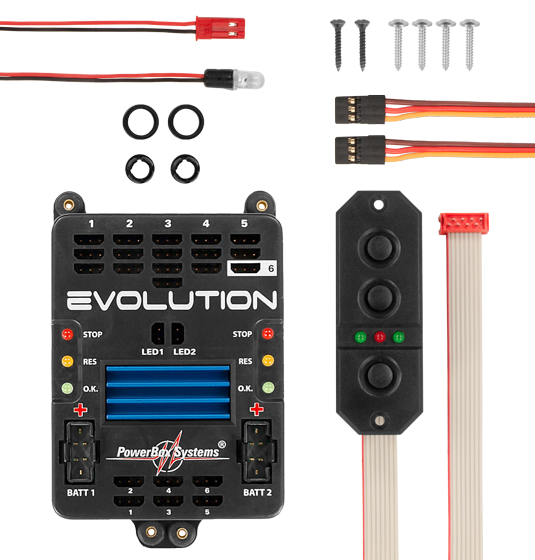
- PowerBox Evolution
- SensorSwitch
- 6 patch leads
- 2 external LEDs
- 4 rubber grommets and brass spacers
- 4 retaining screws
- Operating instructions in german and english
|
|
|
|
|
|
Product description
|
The PowerBox Evolution is always the first choice when a small, robust battery backer system is required: the typical range of applications extends from warbirds to 3D aerobatic models and even to jets.
The first series of the Evolution was introduced back in the year 2004, and since that time it has been continuously developed and improved. For example, the current version provides six remotely accessed channels. The capacity of the regulators has also been significantly increased by redesigning the whole base plate to act as a heat-sink. The output voltage can now be set to 5.9 V or 7.4 V, which means that the Evolution is an excellent choice for standard 6.0 V servos as well as HV systems. In both cases the constant output voltage ensures consistent running and extended effective life for your servos.
The unit is switched on using the SensorSwitch which is included in the set as standard; the procedure could hardly be simpler: pressing the SET button prepares the switching process, and a brief press on buttons I and II actually switches on the two power circuits.
|
|
This effectively eliminates the danger of switching the backer on or off accidentally, and provides a means of switching and checking both switched circuits independently of each other.
The SensorSwitch is also used to enter the battery type; this information is required for the integral battery indicator. The two rows of LEDs indicate the state of charge of the batteries in four stages. The backer also includes a minimum voltage memory which stores the lowest voltage value which occurs during a flight, enabling the pilot to monitor his batteries more accurately. After the flight the minimum value can be read from the LEDs by pressing buttons I and II.
The Evolution is fitted with integral signal amplifiers and RF interference suppressors to ensure that signal strength to the servos is adequate when long extension leads are used. To prevent possible interaction between the servos, the backer is fitted with a circuit which effectively suppresses any servo feedback currents which might occur.
|
|
Operating instructions (4230_Evolution_en.pdf, 347 Kb) [Λήψη]
Test report (rcme201305.pdf, 932 Kb) [Λήψη]


